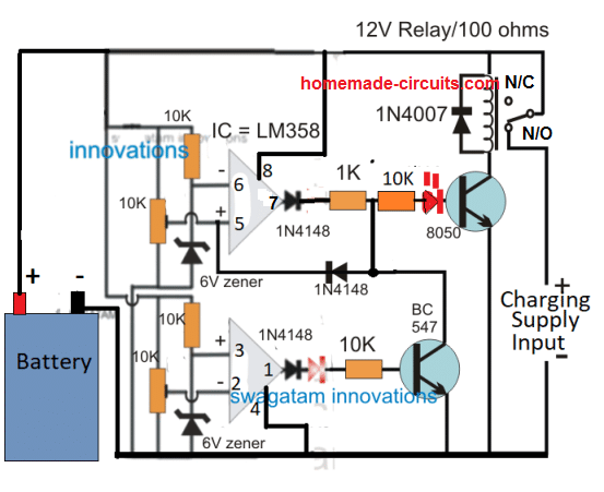
Split Charge Relay Circuit Diagram
This is how you can install your split charge relay.
Split charge relay circuit diagram. Ensure this cable is thick enough to carry the maximum charging current of your alternator. One should go in between the lead that goes from the starter battery to the split charge relay and one between the split charge. The relay will then switch in the alternator feed to the leisure battery to let it charge just like the vehicle starter battery. To fit a split charge relay first connect a 16sqmm red cable from the positive terminals of each battery bank to the large studs on the relay labelled 87 and 30.
Instillation guide for a 12v voltage sense split charge relay system thank you for purchasing this kit from simply split charge. A 12 volt relay is the same type of relay that you would find in many 12 volt electrical systems. Have a look at the diagram above to see the basic wiring diagram of your voltage sensed split charge kit. The other and much easier method is to use a volt sensing circuit which detects a rise in voltage when engine running and energises the coil of a split charge relay to charge the leisure battery.
I have left boxes on the diagram on the left to help you with your measurements. Whatever split charge system you opt for the most important aspect is to ensure that all connecting cables are protected by appropriately rated fuses to prevent an electrical fire. How does a 12 volt relay work. Existing wiring not shown for clarity.
Fit a fuse to one of these cables rated. Protecting your split charge circuit. Each battery that connects into the split charge device should have an appropriately rated fuse installed in line with the.


